
All Products


Vishay IRL510PBF
IRL510PBF
-
69823526-IRL510PBF
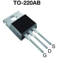
Transistor MOSFET N-CH 100V 5.6A 3-Pin (3 Tab) TO-220AB
- MountThrough Hole
- Number of Pins3
- Weight6.000006 g
- Case/PackageTO-220AB
- Voltage Rating (DC)100 V
- Turn Off Delay Time
It is the time from when Vgs drops below 90% of the gate drive voltage to when the drain current drops below 90% of the load current. It is the delay before current starts to transition in the load, and depends on Rg. Ciss.
16 ns - Schedule B8541290080, 8541290080|8541290080|8541290080|8541290080|8541290080
- RoHSCompliant
- Number of Elements1
- Fall Time18 ns
- Packaging
Semiconductor package is a carrier / shell used to contain and cover one or more semiconductor components or integrated circuits. The material of the shell can be metal, plastic, glass or ceramic.
Bulk - Resistance540 mΩ
- Max Operating Temperature
The Maximum Operating Temperature is the maximum body temperature at which the thermistor is designed to operate for extended periods of time with acceptable stability of its electrical characteristics.
175 °C - Min Operating Temperature-55 °C
- Max Power Dissipation
The maximum power that the MOSFET can dissipate continuously under the specified thermal conditions.
43 W - Current Rating
Current rating is the maximum current that a fuse will carry for an indefinite period without too much deterioration of the fuse element.
5.6 A - Number of Channels1
- Element Configuration
The distribution of electrons of an atom or molecule (or other physical structure) in atomic or molecular orbitals.
Single - Power Dissipation
the process by which an electronic or electrical device produces heat (energy loss or waste) as an undesirable derivative of its primary action.
43 W - Turn On Delay Time
Turn-on delay, td(on), is the time taken to charge the input capacitance of the device before drain current conduction can start.
9.3 ns - Rise Time
In electronics, when describing a voltage or current step function, rise time is the time taken by a signal to change from a specified low value to a specified high value.
47 ns - Drain to Source Voltage (Vdss)100 V
- Continuous Drain Current (ID)5.6 A
- Threshold Voltage2 V
- Gate to Source Voltage (Vgs)10 V
- Drain to Source Breakdown Voltage100 V
- Input Capacitance
The capacitance between the input terminals of an op amp with either input grounded. It is expressed in units of farads.
250 pF - Recovery Time130 ns
- Drain to Source Resistance540 mΩ
- Rds On Max540 mΩ
- Nominal Vgs2 V
- Length10.41 mm
- Height9.01 mm
- Width4.7 mm
- REACH SVHCNo SVHC
- Radiation Hardening
Radiation hardening is the process of making electronic components and circuits resistant to damage or malfunction caused by high levels of ionizing radiation, especially for environments in outer space (especially beyond the low Earth orbit), around nuclear reactors and particle accelerators, or during nuclear accidents or nuclear warfare.
No - Lead FreeLead Free
- Datasheets :
Quantity
Unit Price
Ext. Price
1+
$28.933421
$28.93
10+
$27.295666
$272.99
100+
$25.750660
$2,575.03
500+
$24.293037
$12,146.46
1000+
$22.917983
$22,918.01
* The above prices does not include taxes and freight rates, which will be calculated on the order pages.

SI3469DV-T1-GE3
VishayTrans Mosfet P-ch 20V 5A 6-PIN TSOP T/r
IRLI520GPBF
VishayMosfet N-ch 100V 7.2A TO220FP
SQUN702E-T1_GE3
VishayTrans MOSFET N/P-CH 40V/200V/40V 30A/20A/30A Automotive 10-Pin Triple die T/R
SQUN700E-T1_GE3
VishayTransistor MOSFET Array N-CH/P-CH/N-CH 40V/40V/200V 30A/30A/16A 10-Pin DIE
IRFB9N65A
VishayMosfet N-ch 650V 8.5A TO-220AB
IRFI740G
VishayPower MOSFET(Vdss=400V
SI6955DQ-T1
VishaySmall Signal Field-Effect Transistor
IRFPE40
VishayMosfet N-ch 800V 5.4A TO-247AC
SI2307DS-T1
VishayMOSFET
SQS423ENW-T1_GE3
VishayMosfet