
All Products


Vishay IRLI520GPBF
IRLI520GPBF
-
69822994-IRLI520GPBF
Mosfet N-ch 100V 7.2A TO220FP
- MountThrough Hole
- Number of Pins3
- Weight6.000006 g
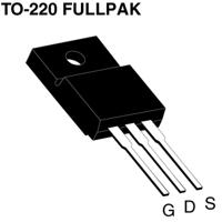
- Case/PackageTO-220-3
- Fall Time27 ns
- RoHSCompliant
- Turn Off Delay Time
It is the time from when Vgs drops below 90% of the gate drive voltage to when the drain current drops below 90% of the load current. It is the delay before current starts to transition in the load, and depends on Rg. Ciss.
21 ns - Packaging
Semiconductor package is a carrier / shell used to contain and cover one or more semiconductor components or integrated circuits. The material of the shell can be metal, plastic, glass or ceramic.
Bulk - Max Operating Temperature
The Maximum Operating Temperature is the maximum body temperature at which the thermistor is designed to operate for extended periods of time with acceptable stability of its electrical characteristics.
175 °C - Min Operating Temperature-55 °C
- Max Power Dissipation
The maximum power that the MOSFET can dissipate continuously under the specified thermal conditions.
37 W - Number of Channels1
- Element Configuration
The distribution of electrons of an atom or molecule (or other physical structure) in atomic or molecular orbitals.
Single - Turn On Delay Time
Turn-on delay, td(on), is the time taken to charge the input capacitance of the device before drain current conduction can start.
9.8 ns - Rise Time
In electronics, when describing a voltage or current step function, rise time is the time taken by a signal to change from a specified low value to a specified high value.
64 ns - Drain to Source Voltage (Vdss)100 V
- Continuous Drain Current (ID)7.2 A
- Gate to Source Voltage (Vgs)10 V
- Drain to Source Breakdown Voltage100 V
- Input Capacitance
The capacitance between the input terminals of an op amp with either input grounded. It is expressed in units of farads.
490 pF - Drain to Source Resistance270 mΩ
- Rds On Max270 mΩ
- Height9.8 mm
- Length10.63 mm
- Width4.83 mm
- Radiation Hardening
Radiation hardening is the process of making electronic components and circuits resistant to damage or malfunction caused by high levels of ionizing radiation, especially for environments in outer space (especially beyond the low Earth orbit), around nuclear reactors and particle accelerators, or during nuclear accidents or nuclear warfare.
No - Lead FreeLead Free

SI7478DP-T1-GE3
Vishay IntertechnologiesPower Field-Effect TransistorSI7143DP-T1-GE3
Vishay IntertechnologiesDescription: Power Field-Effect TransistorSIR422DP-T1-GE3
Vishay IntertechnologiesDescription: Power Field-Effect TransistorSI7489DP-T1-GE3
Vishay IntertechnologiesPower Field-Effect TransistorSIZF914DT-T1-GE3
Vishay IntertechnologiesPower Field-Effect TransistorSI4160DY-T1-GE3
Vishay IntertechnologiesSmall Signal Field-Effect Transistor
IRF540PBF
Vishay IntertechnologiesPower Field-Effect TransistorSQJ418EP-T1_GE3
Vishay IntertechnologiesPower Field-Effect TransistorIRL640
Vishay IntertechnologiesPower Field-Effect TransistorSIR626DP-T1-RE3
Vishay IntertechnologiesPower Field-Effect Transistor