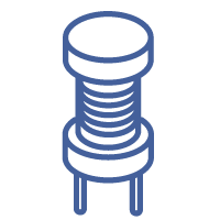
Epcos B82144A2105J
B82144A2105J
5.2 mm x 12 mm
28892587-B82144A2105J
- Package / Case5.2 mm x 12 mm
- Surface Mount
having leads that are designed to be soldered on the side of a circuit board that the body of the component is mounted on.
NO - Terminal ShapeWIRE
- Shape/Size DescriptionTUBULAR PACKAGE
- Number of Terminals2
- Core Material
Core materials are produced in a variety of forms including end-grain balsa wood, PVC foam, urethane foam, non-woven core fabrics, and various types of honeycomb materials.
Ferrite - Function / FeatureCommon Mode
- Length (Max.) / mm31.3
- Width (Max.) / mm18.5
- Height (Max.) / mm33.2
- Rated Voltage [DC] / V800V
- Rated Voltage [AC] / Vrms250V
- Rated Temperature / °C70℃
- AEC-Q200No
- Operating Temperature Range (Min.) / °C-40℃
- Operating Temperature Range (Max.) / °C125℃
- RemarksLead spacing 15 x 12.5 (mm)
- Product Depth (mm)Not Required(mm)
- DC Resistance3.8(ohm)
- Operating Temp Range-55C to 125C
- Quality Factor60
- Product Diameter (mm)5.2(mm)
- Tolerance (+ or -)5%
- Rad HardenedNo
- Maximum DC Current200 mA
- Maximum Operating Temperature
the maximum body temperature at which the thermistor is designed to operate for extended periods of time with acceptable stability of its electrical characteristics.
+ 125 C - Unit Weight0.038801 oz
- Minimum Operating Temperature- 55 C
- Factory Pack QuantityFactory Pack Quantity1500
- Mounting StylesPCB Mount
- Part # AliasesB82144A2105J000
- ManufacturerEPCOS / TDK
- BrandEPCOS / TDK
- Maximum DC Resistance3.8 Ohms
- RoHSDetails
- Q Minimum60
- Operating Temperature-Min-55 °C
- Operating Temperature-Max125 °C
- Rohs CodeYes
- Manufacturer Part NumberB82144-A2105-J
- Part Life Cycle CodeActive
- Ihs ManufacturerEPCOS AG
- Risk Rank0.98
- Special FeaturesQ MEASURED AT 0.252 MHZ
- Packaging
Semiconductor package is a carrier / shell used to contain and cover one or more semiconductor components or integrated circuits. The material of the shell can be metal, plastic, glass or ceramic.
Tape and Reel - SeriesB82144A
- Tolerance5 %
- JESD-609 Codee3
- Pbfree CodeYes
- TerminationStandard
- ECCN CodeEAR99
- TypeB82724J8*N
- Terminal FinishTin (Sn)
- ApplicationsGeneral use
- HTS Code
HTS (Harmonized Tariff Schedule) codes are product classification codes between 8-1 digits. The first six digits are an HS code, and the countries of import assign the subsequent digits to provide additional classification. U.S. HTS codes are 1 digits and are administered by the U.S. International Trade Commission.
8504.50.80.00 - SubcategoryInductors, Chokes & Coils
- TechnologyDRUM CORE
- ShieldingUnshielded
- Number of Functions1
- Reach Compliance Codecompliant
- Current Rating
Current rating is the maximum current that a fuse will carry for an indefinite period without too much deterioration of the fuse element.
1.6A - Military StandardNot Required
- Termination StyleAxial
- Failure Rate
the frequency with which an engineered system or component fails, expressed in failures per unit of time. It is usually denoted by the Greek letter λ (lambda) and is often used in reliability engineering.
Not Required - Lead Spacing
the distance between two baselines of lines of type. The word 'leading' originates from the strips of lead hand-typesetters used to use to space out lines of text evenly. The word leading has stuck, but essentially it's a typographer's term for line spacing.
Not Required(mm) - Lead Diameter0.8 mm
- Inductance47mH
- Test Frequency
a statistical procedure for assessing data that contain counts or the numbers of occurrences of various categories or classes.
0.1(MHz) - Impedance
In electrical engineering, impedance is the opposition to alternating current presented by the combined effect of resistance and reactance in a circuit.
Not Required(ohm) - Lead StyleAxial
- Inductor ApplicationRF INDUCTOR
- Terminal PlacementAXIAL
- Quality Factor-Min (at L-nom)60
- Inductor TypeGENERAL PURPOSE INDUCTOR
- Product Type
a group of products which fulfill a similar need for a market segment or market as a whole.
Fixed Inductors - ShieldedNO
- Rated Current-Max0.2 A
- Inductance-Nom (L)1000 µH
- DC Current200(mA)
- DesignCurrent-compensated ring core choke (double)
- Number of LinesDouble Choke
- Self Resonant Frequency
The self resonant frequency of an inductor is the frequency at which the parasitic capacitance of the inductor resonates with the ideal inductance of the inductor resulting in an extremely high impedance. At this frequency the device looks like an open circuit.
1.2(MHz) - Core TypeDrum
- ProductRF Inductors
- Saturation Current-
- Product Length (mm)14.8(mm)
- Length31.30mmMax.
- Width18.50mmMax.
- Height33.20mm Max.
- Diameter5.2 mm
- Product Height (mm)Not Required(mm)


